samedi 20 novembre 2021

Attempt to design an alternative I5R

Attempt to design an alternative I5R

1.Purpose

As we saw in the article on the observation of an I5R, Olight made certain choices to evolve the i5T in I5R. The purpose of this article is to think yourself as an Odesigner and try to make different choices.

2.Specifications

 Regarding the mechanics, we will start with the same choice and keep exactly the same. The only thing to modify is (if it is possible):


Regarding the batteries, it must accept:

  • Alkaline battery AA
  • NimH AA
  • Lithium AA
  • 14500 3.6V Lithium battery

For the light power, we will try to keet it equivalent for AA and go to higher for 14500.

3.Analysis of the specifications

 As we saw in the observation of the i5R, this will force us to hace a so-called Buck-Boost voltage conversion topology, The bulk of the work be at this level because the available space is low.

Then Olight always delivers a battery with lamps, thus we will have to find a good 14500. As we are ambitious and we are going to try to get a lot of lumens, we will choose a model with very low internal resistance and a relatively high capacity.

As we want to output high power the temperature may be our main problem, indeed the user should not burn himself.

We will start with the battery, the the electronics ans its integration and  the thermal will be measured which will allow things to be corrected if it is too hot.

4.Battery

 For the battery, we will choose a Vapcell INR14500 H10, It seems to be a very good candidate and in addition, I have this model.

Its internal resistance is about 0.07Ohm and the capacity is 1000mAh, copared with the Baton 3 16340, it is more efficient. This is rather a good omen because the Baton 3 can draw up to 1200 lumens.

It can delivers 10A continuously and much more over shorter times.

But be careful with this battery fully charged in a normal I5T, the electronics of the lamp are destroyed on the fisrt switch.

5.Electronics

 If you haven't already read it, I recommended you the following 2 articles

So as we have seen:

  • Space available in an I5T is extremely low.
  • Schematic of a Buck-Boost requires more space than a Boost (I5T) and I have not found integrated circuit which fulfills this function at very low voltage.
  • In the S1R Baton II, Olight used a Boost followed by a linear regulator which takes up little space but which can lead to significant losses.

5.1.Electronics choice

As I can hardly see myself starting from zero for a discrete solution (no control integrated circuit + switching MOSFET) in such a small volume, we will go for a similar choice to that of Olight S1R Baton II. The advantage is to have only one "big" transistor to add and some slight electronic modifications. But this transistor will be hot ant it will have to be thermally transferred.

Regarding the light power we will also base ourselves on the baton II, whose maximum LED current is 3A, and start at 2A, given the difference in the volume of material between I5T et S1R to arrive at an equivalent heating.

5.2.Modifications compared to I5T

I5T Mode are:

We will quickly see that we will have to change that. Indeed the maximum power of the I5T is the same regardless of the battery voltage. We want to try to reach 2A which correspond to a LED voltage of 3,2V which gives 6,4W. However at 0,9V input voltage a Boost has a maximum efficiency of 80% which leads to a current of 8,9A (which is totally incompatible with standard AA an integrated Boost circuit of I5T).

It will therefore be necessary to modify the actual schematic so that the maximum current depends on the voltage of the battery. And we will therefore keep the decrease over time and the gradual changes (i.e. 100% for 3min, then 50% for 25min, then 10%) with each of the 3 progressive transitions. For LOW mode, 15 lumens correspond to 4%.

5.2.1.Current variation in the LED as a variation of its voltage

In principle, the micro-controller outputs a PWM signal which is averaged by a low-pass filter. This average is used as a reference for the error amplifier which compares it to the voltage of the shunt (image of the current in the LED). And so the output of the error amplifier attacks the driving of the boost. The electrical schematics of the I5T is therefore as follows:

The micro-controller being powered by the Boost output via a 3V LDO, its high voltage state voltage varies slightly between 2,65V and 3V but it is far from being enough for our modification.

Here is the schematic on which we will start for our alternative design of the I5R:

Adding R4, R7, R11 and CR1 gives us the following theoretical curves:
On the x-axis we have the battery voltage. Compare the yellow curve (current I5T 100%) and the blue curve (I5R alternative 100%). We see that the curves intersect towards 1,25V in fact I chose this voltage because I wanted equivalent result with NiMH batteries, which means that we will get almost 800mA with a 1,5V battery (which is equivalent to 350 lumen).
As for the temporal, we should have the blue curve for "min, then the red curve for 25min then the green curve if the battery allows it.

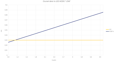
The curve for the LOW mode is as follows:

5.2.2. Shunt resistor

As the schematic shows us, we are going to stay on the same value which will allow the heat to de distributed and the MOS Q1 to be a little heated less. However 2A in a resistor of 0,05Ohm gives 0,2W, it is a bit to much for a 0805, thus we are going to switch to a 1206 (bigger size).

5.2.3.Inductor

The L1 inductor is already a very good inductor and should drawn 2A current with no problem (I measured its internal resistance at 0,011Ohm). However the height of this component is 3,3mm, and we need an inductor of 2,3mm max to manage the thermal of Q1. We will therefore start with a model form the manufacturer BOURNS, an  SRP4018FA-R68M which has a heigh of 1,8mm +/- 0,2mm.

5.2.4.MOSFET Q1

I won't go into the explanations too much, but we needed a MOS with a VGS threshold max of 1V, the lowest possible RDSon, a small case with good thermal resistance (see bellow). My choice fell on the SISS61DN from VISHAY.

This component is the most critical, because it is it that will take most of the voltage between the LED and the battery with a 14500. A numerical application will be more meaningful, when the battery is fully charged, its voltage is 4,2V and the LED is 3V for 2A (most critical case). The electronics will therefore manage to present a resistance of 1,2V / 2A (i.e. 0,6 Ohm). These 0,6Ohm are distributed between inductor (0,0082Ohm), IC1 (0,058Ohm), Q1 (the remainder) and the shunt (0,05Ohm). So that is 0,4838Ohm for the Q1 so almost 2W of losses.

In a classic I5T, the LED in which there is about 1,82W is mounted on IMS (Insulated metallic substrate) and not PCB. So if we do not want this MOS to break with high temperature, we will have to transfer it thermally.

5.2.5.PCB with modification

 New component with red Marking

5.3.Measure after modification


In yellow the battery voltage and in green the current in the LED. 

We see:

  • a plateau at the level of the current towards the beginning, which is due to an approximation in my theoretical calculations. To remedy this it would be necessary to decrease the voltage across R4, however I think 1.85A is sufficient for this test.
  • the green line which suddenly thickens towards 3V is when we go from Buck to Boost.
  • that it is rather in accordance with the theory

On the I5R OLIGHT announces 350lumens with a current of 800mA. 

If we look at the datasheet of the LED going from 800A to 1.85A we should have a flux of about 700lumens to 1.85A.

6.Assembly 

We saw on the I5R that to manage the thermal the LED was mounted on an IMS then transferred using thermal grease on an aluminum part which is inserted by force into the body of the I5R.
The principle for our test is to be able to put an SMI on each side of the aluminum part, one for the LED and the other for the transistor Q1. The other advantage of this solution is to increase the thickness of the aluminum part by 30% and therefore this will make it possible to reduce the temperature gradient between the body of the I5T and the elements which heat up. The drawing below shows us this assembly.

It looks simple on paper but seen the actual size it looks like a very tight part of TETRIS😀.
A photo of the IMS with the MOS Q1, some small components and the 3 connections to the modified PCB of the I5T (sorry for the quality).

The change of the inductor will allow us to place the PCB with the electronics in its initially planned place. To prevent the inductor, the Boost integrated circuit and the shunt resistor from getting too hot in HIGH mode, I add a thermal Gappad to their level. In the photo below we do not see the difference with a classic I5T.
All that remains is to insert it by force into the body of an I5T and off to testing😎.

7.Thermal

As a reminder:
This is the weak point of this test, because I cannot modify the times of the operating modes. 
The images below are taken with the thermal imager and the time at which they are taken is indicated below.

If we look at the 3min and 3min30 pictures we see the impact of the change from 100% to 50%. Indeed the temperature of the head decreased while the temperature of the body continued to rise.

It is the same thing between 20min and 25min with the change from 50% to 10%. 

The temperature rises to 55 ° C (burning sensation) however this temperature is maximized because if the lflashlight had been held in one hand there would have been a heat exchange and we would have climbed lower. 

After 45min of HIGH mode, the battery voltage is 3.33V which means that there is approximately 19% battery charge remaining.

8.Rendering

In this photo we have an I5R in HIGH mode and our modified I5T in HIGH mode.

The 2 flashlights are placed 40cm from the screen.

9.Conclusion

This attempt is rather conclusive, changing the time to 100% in HIGH mode would be fine. However as expected, the integration is complicated with a min clearance of 0.2mm. It is really not easy to industrialize for me I had a hard time making this prototype. So I understand why Olight did not go for this choice.


vendredi 19 novembre 2021

Essai de conception alternative d'une OLIGHT I5R

Essai de conception alternative d'une Olight I5R

1.But

Comme nous l'avons vu dans l'article sur l'observation d'une I5R, Olight a fait certains choix pour faire évoluer la I5T en I5R. Le but de cet article est de se prendre pour un Odesigner et de tenter de faire des choix différents.

2.Cahier des charges

Concernant la mécanique nous allons partir sur le même choix et garder exactement la même mécanique. Donc la seule partie que nous allons pouvoir modifier si c'est possible est l'intérieur de cette pièce:

Au sujet des batteries acceptées, nous allons partir sur:

AA standard alcalines et salines

AA NiMH 

AA Lithium 1,5V non rechargeable

14500 Li-ion 3.6V standard

Pour la puissance lumineuse nous allons essayer de la garder équivalente pour les AA et de passer à une puissance supérieure pour les 14500.

3. Analyse du cahier des charges

Comme nous l'avons vu dans l'observation de la I5R cela va nous contraindre à avoir une topologie de conversion de tension dite Buck-Boost, le gros du travail va être à ce niveau car la place disponible est faible.

Ensuite comme Olight livre toujours une source d'alimentation avec ces lampes, il va falloir trouver une 14500. Comme nous sommes ambitieux et que nous allons essayer de sortir beaucoup de puissance on va choisir un modèle avec une résistance interne très faible et une capacité relativement forte.

Comme nous voulons sortir une puissance forte, la température risque d'être notre principal problème, en effet l'utilisateur ne doit pas se brûler.


Nous allons commencer par la batterie, puis l'électronique et son intégration et la thermique sera plus mesurée ce qui permettra de corriger les choses si elle est trop élevée.

4.Batterie

Pour la batterie on va s'orienter vers une Vapcell INR14500 H10, elle me semble une très bonne candidate et en plus  je dispose de ce modèle.

 
La résistance interne est d'environ 0,07Ohm et la capacité est de 1000mAh, en comparaison avec la batterie 16340 de la S1R baton II, elle est plus performante. C'est plutôt de bonne augure car la S1R baton II à  une puissance max de 1000lm. Elle délivre 10A en continu sur un décharge complète et beaucoup plus sur des temps plus courts.

 Attention avec cette batterie complètement chargée dans une I5T normale, on détruit l'électronique de la lampe dès le premier appui sur l'interrupteur.

5. L'électronique

Si ce n'est pas déjà fait je vous invite à lire les 2 articles suivants pour bien comprendre la suite:

Observation I5R

Fonctionnement d'une lampe, cas de la Olight S1R baton II

Donc comme nous l'avons vu:

la place disponible dans une I5T est extrêmement faible.

le schéma d'un Buck-Boost demande plus de place qu'un Boost  (I5T) et je n'ai pas trouvé de circuit intégré qui remplisse cette fonction à  nos tensions d'utilisation (0,9V-4,2V)

Olight dans la S1R Baton II à utilisé une structure de Boost suivi d'un régulateur linéaire qui permet de prendre peu de place mais qui peu conduire à des pertes importantes.

5.1. Choix pour l'électronique

Comme je me vois mal partir de zéro pour une solution discrète (pas de circuit intégré contrôle + MOS de découpage) dans un si petit volume, nous allons partir pour un choix identique à  celui de la S1R Baton II, l'avantage est de n'avoir à  rajouter qu'un seul transistor cependant celui va avoir quelques contraintes.

Concernant la puissance lumineuse on va se baser aussi sur la S1R Baton II, dont le courant maximal est de 3A, et partir sur 2A au vu de la différence du volume de matière entre la I5T et la S1R pour arriver à  un échauffement équivalent.

5.2 Modifications par rapport à la I5T

Les modes de fonctionnement sont les suivants:

On va vite voir qu'il va falloir changer ça. En effet la puissance maximale de la I5T est la même quelque soit la tension de la batterie. Nous voulons essayer d'atteindre 2A ce qui correspond à une tension de LED de 3,2v ce qui donne 6,4W. Cependant à 0,9V un Boost à un rendement au maximum de 80% ce qui conduit à  un courant de 8,9A qui est totalement incompatible avec des AA standards et le circuit Boost intégré.

Il va donc falloir modifier le schéma actuel pour que le courant maximal dépende de la tension de la batterie. Et nous allons donc garder la décroissance avec le temps et les changements progressifs, c'est à  dire 100% pendant 3min puis 50% pendant 25min puis 10% avec chacune des 3 transitions progressive. Pour le mode LOW les 15 lumens correspondent à 4%.

5.2.1.Variation du courant dans la LED en fonction de sa tension

Dans le principe micro-contrôleur sort un signal PWM dont un filtre passe-bas fait la moyenne. Cette moyenne sert de référence à l'amplificateur d'erreur qui la compare à la tension aux bornes du shunt image du courant dans la LED. Et donc la sortie de l'amplificateur d'erreur attaque le pilotage du boost. Le schéma de la I5T est donc le suivant:

Le micro-contrôleur étant alimenté par la sortie du Boost via un LDO de 3V, sa tension à l'état haut varie légèrement entre 2.65V et 3V mais c'est loin d'être assez pour notre modification.

Voici donc le schéma sur lequel nous allons partir pour notre conception alternative de la I5R:


L'ajout de R4, R7, R11 et CR1 nous donne les courbes suivantes:

En abscisse nous avons la tension de la batterie. Il faut comparer la courbe jaune (I5T actuelle 100%) et la courbe bleu (I5R alternative 100%). On voit que les courbes se croisent vers 1.25V en effet j'ai choisi cette tension car je voulais un résultat équivalent avec les batteries NiMH, ce qui fait que nous obtiendront presque 800mA avec une pile de 1.5V ce qui équivaut à 350 lumens.

En ce qui concerne le temporel, nous devrions avoir la courbe bleue pendant 3 min, puis la courbe rouge pendant 25min, puis la courbe verte si la batterie le permet.

La courbe pour le mode "LOW" est la suivante:

5.2.2.Résistance de shunt

Comme le schéma nous le montre, nous allons rester sur la même valeur ce qui va permettre de répartir la chaleur et de moins faire chauffer le MOS Q1. Cependant 2A dans une résistance de 0.05R cela fait 0.2W, c'est un peu trop pour une 0805, nous allons passer sur une 1206.

5.2.3.Inductance

L'inductance L1 est déjà une très bonne inductance, j'ai mesuré sa résistance interne à 0.011Ohm, cependant la hauteur de ce composant est de 3.3mm et j'ai besoin d'une inductance de 2.3mm max pour gérer la thermique de Q1. On va donc partir sur un modèle du fabricant BOURNS une SRP4018FA-R68M qui a une hauteur de 1.8mm +/-0.2mm.

5.2.4.MOSFET Q1

Je ne vais pas rentrer trop dans les explications, mais il fallait un MOS avec un VGS threshold max de 1V, un RDSon le plus faible possible, un boîtier petit avec une bonne résistance thermique (voir ci-dessous). Mon choix s'est porté sur le SISS61DN de Vishay.

Ce composant est le plus critique, car c'est lui qui va encaisser la majeure partie de la tension entre la LED et la batterie avec une 14500 Li-ion. Une application numérique va être plus parlante, quand la batterie est chargée à fond sa tension est de 4.2V et la LED 3V pour 2A. L'électronique va donc s'arranger pour présenter une résistance de 1.2V/2A c'est à dire 0.6Ohm. Ces 0.6Ohm se répartissent entre la self(0.0082Ohm), IC1(0.058Ohm), Q1(le reste) et le shunt(0.05). Ça fait donc 0.4838Ohm pour le MOS donc presque 2W de pertes.

Dans une I5T classique la LED dans laquelle il y a environ 1.82W est montée sur SMI. Donc si on ne veut pas que ce MOS casse en température il va falloir le reporter thermiquement.

5.2.5.Résultat des modifications

Les composants modifiés sont indiqués en rouge


5.3.Mesure après modification

En jaune la tension de la batterie et en vert le courant dans la LED.

On aperçoit:

  • un plateau au niveau du courant vers le début, qui est du a une approximation dans mes calculs théoriques. Pour y remédier il faudrait diminuer la tension aux bornes de R4, cependant je pense que 1.85A suffit pour cet essai.
  • la ligne verte qui s'épaissit tout d'un coup vers 3V, c'est quand on passe du Buck au Boost.
  • que c'est plutôt conforme à la théorie
Sur la I5R OLIGHT annonce 350lumens avec un courant de 800mA.
Si on regarde la datasheet de la LED en passant de 800A à 1.85A on doit avoir un flux d'environ 700lumens à 1.85A.

6.Assemblage


Nous avons vu sur la I5R que pour gérer la thermique la LED était monté sur un SMI puis reportée à l'aide de graisse thermique sur une pièce en aluminium qui est insérée en force dans le corps de la I5R.

Le principe pour notre essai est de pouvoir mettre un SMI de chaque côté de la pièce en aluminium, un pour la LED et l'autre pour le transistor Q1. L'autre avantage de cette solution est d'augmenter de 30% l'épaisseur de la pièce en aluminium et donc cela va permettre de diminuer le gradient de température entre le corps de la I5T et les éléments qui chauffent. Le dessin ci-dessous nous montre ce montage.

Ça à l'air simple sur le papier mais vu la taille réelle, ça ressemble à une partie de TETRIS très serrée 😀.
 
Une photo du SMI avec le MOS Q1, quelques petits composants et les 3 connections vers le PCB modifié de la I5T(désolé pour la qualité).

Le changement de l'inductance va nous permettre disposer le PCB avec l'électronique à sa place initialement prévue. Pour éviter que le inductance, le circuit intégré du Boost et la résistance shunt ne chauffent trop en mode HIGH je rajoute un Gappad thermique à leur niveau. Sur la photo ci-dessous on ne voit pas la différence avec une I5T classique.

Il ne reste plus qu'à l'insérer en force dans le corps d'une I5T et en route pour les essais😎.

7.Thermique

Pour rappel:

C'est le point faible de cet essai, car je ne peux modifier les temps des modes de fonctionnement.

Les images ci-dessous sont prises à la caméra thermique et le moment auquel elles sont prise est indiqué en dessous.


Si on regarde les clichés 3min et 3min30 on voit l'impact du passage de 100% à 50%. En effet la température de la tête a diminué alors que la température du corps continué de monter.

C'est la même chose entre 20min et 25min avec le passage de 50% à 10%.

La température monte jusqu'à 55°C (sensation de brûlure) cependant cette température est maximisée car si la lampe avait été maintenue dans une main il y aurait eu un échange thermique et nous serions monté moins haut.

Après 45min de mode HIGH, la tension batterie est de 3.33V ce qui veut dire qu'il reste approximativement 19% de charge de batterie.

8.Rendu

Sur cette photo nous avons une I5R en mode HIGH et notre I5T modifiée en mode HIGH.

Les 2 lampes sont disposée à 40cm de l'écran.

8.Conclusion

L'essai est plutôt concluant, en modifiant le temps à 100% en mode HIGH se serait bien. Cependant comme prévu, l'intégration est compliquée avec un jeu min de 0.2mm. Ce n'est vraiment pas facile à industrialiser pour ma part j'en ai bavé pour réaliser ce prototype. Je comprends donc pourquoi Olight ne s'est pas dirigé vers ce choix.


I3T et I5T avec des batteries 3.6V

 I3T et I5T avec des batteries 3.6V   1.Introduction Bonjour, je vous propose aujourd'hui un petit article sur une question que beaucoup...